


All Products
Contact Person :
Zhou
Phone Number :
+86 15019457904
Whatsapp :
+8615019457904
FPC Flex Rigid PCB Multilayers Printed Circuit Boards For Electronics


| Place of Origin | Shenzhen |
|---|---|
| Brand Name | YScircuit |
| Certification | ISO9001,UL,REACH, RoHS |
| Model Number | YS-0036 |
| Minimum Order Quantity | 1 piece |
| Price | 0.02-1.98$/piece |
| Packaging Details | Foam cotton + carton + strap |
| Delivery Time | 2-8 days |
| Payment Terms | T/T,PayPal, Alibaba pay |
| Supply Ability | 251,000 square meter/year |

Contact me for free samples and coupons.
Whatsapp:0086 18588475571
Wechat: 0086 18588475571
Skype: sales10@aixton.com
If you have any concern, we provide 24-hour online help.
xProduct Details
| Material | FR4, Polymide | Size | 18*8cm |
|---|---|---|---|
| Process | Immersion Gold | Surface Finishing | HASL/HASL-LF/ENIG |
| Min. Line Width | 4mii | Board Thickness | 0.8mm |
| Color | Green | Name | Electronics Pcb |
| High Light | Flex Rigid PCB Printed Circuit Boards,Multilayers Flex Rigid PCB Circuit Boards,18*8cm Flex PCB Circuit Boards |
||
Product Description
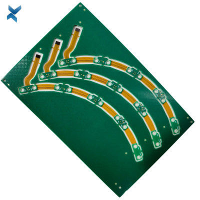
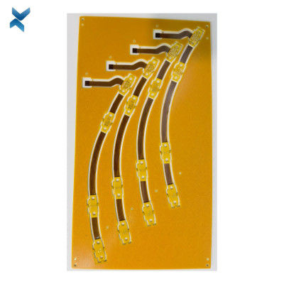
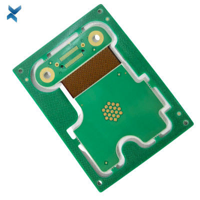
Flex-Rigid PCB FPC Professional Multilayers Printed Circuit Boards For Electronics
What is a Rigid Flex PCB?
Rigid-flex PCBs combine flexible and rigid board technologies, providing optimal solutions for challenging space constraints.
They ensure secure connections between device components, reducing the need for plugs and connectors.
Additionally, they offer advantages like mechanical stability, 3D design freedom, simplified installation, space savings, and consistent electrical characteristics.
YSCircuit Rigid Flex PCB manufacturing capabilities overview
| Feature | capabilities | |
| Layer Count | 2-20L | |
| Rigid-Flex Thickness | 0.3mm-5.0mm | |
| PCB thickness in flex section | 0.08-0.8mm | |
| copper Thickness | 1/4OZ-10OZ | |
| Minimum line Width and Space | 0.05mm/0.05mm(2mil/2mil) | |
| Stiffeners | Stainless steel,PI, FR4 etc. | |
| Material | Polyimide Flex+FR4,RA copper, HTE copper, polyimide, adhesive,Bondply | |
| Min mechanical Drilled Size | 0.15mm(6mil) | |
| Min laser Holes Size: | 0.075mm(3mil) | |
| Surface Finish | Suitable Microwave/RF PCB urface finishes: Electroless Nickel, Immersion Gold, ENEPIG, Lead free HASL,Immersion Silver.etc. | |
| Solder Mask | Green, Red, Yellow, Blue, White, Black, Purple, Matte Black, Matte green.etc. | |
| Covrelay (Flex Part) | Yellow Coverlay, WhiteCoverlay,Black Coverlay | |
| layer/m² | S<1㎡ | S<3㎡ | S<6㎡ | S<10㎡ | S<13㎡ | S<16㎡ | S<20㎡ | S<30㎡ | S<40㎡ | S<50㎡ | S<65㎡ | S<85㎡ | S<100㎡ |
| 1L | 4wds | 6wds | 7wds | 7wds | 9wds | 9wds | 10wds | 10wds | 10wds | 12wds | 14wds | 15wds | 16wds |
| 2L | 4wds | 6wds | 9wds | 9wds | 11wds | 12wds | 13wds | 13wds | 15wds | 15wds | 15wds | 15wds | 18wds |
| 4L | 6wds | 8wds | 12wds | 12wds | 14wds | 14wds | 14wds | 14wds | 15wds | 20wds | 25wds | 25wds | 28wds |
| 6L | 7wds | 9wds | 13wds | 13wds | 17wds | 18wds | 20wds | 22wds | 24wds | 25wds | 26wds | 28wds | 30wds |
| 8L | 9wds | 12wds | 15wds | 18wds | 20wds | 20wds | 22wds | 24wds | 26wds | 27wds | 28wds | 30wds | 30wds |
| 10L | 10wds | 13wds | 17wds | 18wds | 20wds | 20wds | 22wds | 24wds | 26wds | 27wds | 28wds | 30wds | 30wds |
| 12L | 10wds | 15wds | 17wds | 18wds | 20wds | 20wds | 22wds | 24wds | 26wds | 27wds | 28wds | 30wds | 30wds |
| 14L | 10wds | 16wds | 17wds | 18wds | 20wds | 20wds | 22wds | 24wds | 26wds | 27wds | 28wds | 30wds | 30wds |
| 16L | 10wds | 16wds | 17wds | 18wds | 20wds | 20wds | 22wds | 24wds | 26wds | 27wds | 28wds | 30wds |
30wds |
![]()
![]()
![]()
![]()
![]()
FQA
What are the guidelines for designing the rigid and flexible areas of a rigid-flex PCB?
A: The guidelines for designing the rigid and flexible areas of a rigid-flex PCB include maintaining a minimum bend radius, avoiding sharp angles, and ensuring that the copper traces do not extend into the bend area. It is also important to provide adequate support for any components that are mounted in the flexible areas.
What is the difference between a 1-layer and a 2-layer rigid-flex PCB?
A: A 1-layer rigid-flex PCB has a single layer of flexible material sandwiched between two layers of rigid material, while a 2-layer rigid-flex PCB has two layers of flexible material sandwiched between three layers of rigid material. A 2-layer rigid-flex PCB provides more flexibility and better bending performance than a 1-layer rigid-flex PCB.
What are the common connector types used in rigid-flex PCBs?
A: The common connector types used in rigid-flex PCBs include ZIF (zero insertion force) connectors, FPC (flexible printed circuit) connectors, and board-to-board connectors. The choice of connector depends on the specific application and design requirements.
What is the role of adhesive in a rigid-flex PCB?
A: Adhesive is used to bond the rigid and flexible areas of a rigid-flex PCB together. The adhesive must be carefully selected to ensure that it can withstand the intended use and environment, and that it does not interfere with the electrical performance of the board.
What is the difference between a dynamic and a static bend in a rigid-flex PCB?
A: A dynamic bend is a bending or flexing motion that occurs during the normal operation of the device, while a static bend is a fixed or permanent bend that is designed into the board. Dynamic bends require more careful design and testing than static bends, as they can cause fatigue and failure over time.
Recommended Products