


All Products
Contact Person :
Zhou
Phone Number :
+86 15019457904
Whatsapp :
+8615019457904
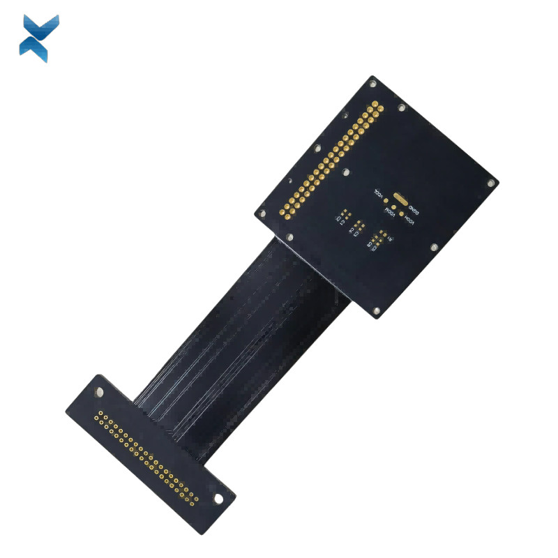
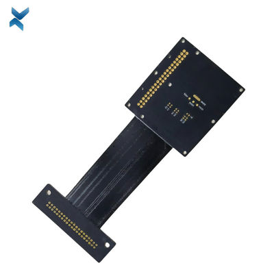
FR4 Polymide Rigid Flex Circuit Boards For Industrial Drilling Equipment


| Place of Origin | Shenzhen |
|---|---|
| Brand Name | YScircuit |
| Certification | ISO9001,UL,REACH, RoHS |
| Model Number | YS-0035 |
| Minimum Order Quantity | 1 piece |
| Price | 0.02-1.98$/piece |
| Packaging Details | Foam cotton + carton + strap |
| Delivery Time | 2-8 days |
| Payment Terms | T/T,PayPal, Alibaba pay |
| Supply Ability | 251,000 square meter/year |

Contact me for free samples and coupons.
Whatsapp:0086 18588475571
Wechat: 0086 18588475571
Skype: sales10@aixton.com
If you have any concern, we provide 24-hour online help.
xProduct Details
| Material | FR4, Polymide | Size | 14*3cm |
|---|---|---|---|
| Process | Immersion Gold | Surface Finishing | HASL/HASL-LF/ENIG |
| Min. Line Width | 4mii | Board Thickness | 0.8mm |
| Color | Black | Name | Drilling Equipment PCB |
| High Light | Polymide Rigid Flex Circuit Boards,FR4 Rigid Flex Circuit Boards,Drilling Equipment FR4 PCB Board |
||
Product Description
FR4 Polymide Rigid Flex Circuit Boards For Industrial Drilling Equipment
Rigid-Flex Circuit Boards Pcb For Drilling Equipment Industrial Products
When it comes to printed circuit boards (PCBs), there are several options to choose from.
While rigid and flexible PCBs have their advantages, rigid-flex PCBs offer distinct benefits, including:
Space optimization in all three dimensions
Reduced weight and space requirements
Better signal transmission reliability
Increased functionality for a wide range of applications
Despite these advantages, the decision to use a flex PCB or fully rigid PCB will ultimately depend on the specific needs of your application.
Our team has the expertise to determine which type of PCB will be the best fit for your project.
Applications of Rigid-Flex PCBs
Rigid-flex PCBs have become increasingly popular across a wide range of electronic products, including:
Automobiles
Cell phones
Green and solar energy devices
IoT devices
Medical equipment
Tools
Wearable devices
Rigid-Flex PCBs vs. Flex PCBs
While rigid-flex PCBs and flex PCBs both offer unique advantages, they differ in their design and functionality.
Rigid-flex PCBs use rigid substrates connected with flexible interconnects, while flex PCBs only employ flexible components.
Some differences
between the two include:
Rigid-flex PCBs offer strong reliability and are well-suited for high-density/limited space applications.
Flex PCBs are better suited for products with unique space or density requirements due to their use of flexible components.
YSCircuit Rigid Flex PCB manufacturing capabilities overview
| Feature | capabilities | |
| Layer Count | 2-20L | |
| Rigid-Flex Thickness | 0.3mm-5.0mm | |
| PCB thickness in flex section | 0.08-0.8mm | |
| copper Thickness | 1/4OZ-10OZ | |
| Minimum line Width and Space | 0.05mm/0.05mm(2mil/2mil) | |
| Stiffeners | Stainless steel,PI, FR4 etc. | |
| Material | Polyimide Flex+FR4,RA copper, HTE copper, polyimide, adhesive,Bondply | |
| Min mechanical Drilled Size | 0.15mm(6mil) | |
| Min laser Holes Size: | 0.075mm(3mil) | |
| Surface Finish | Suitable Microwave/RF PCB urface finishes: Electroless Nickel, Immersion Gold, ENEPIG, Lead free HASL,Immersion Silver.etc. | |
| Solder Mask | Green, Red, Yellow, Blue, White, Black, Purple, Matte Black, Matte green.etc. | |
| Covrelay (Flex Part) | Yellow Coverlay, WhiteCoverlay,Black Coverlay | |
| layer/m² | S<1㎡ | S<3㎡ | S<6㎡ | S<10㎡ | S<13㎡ | S<16㎡ | S<20㎡ | S<30㎡ | S<40㎡ | S<50㎡ | S<65㎡ | S<85㎡ | S<100㎡ |
| 1L | 4wds | 6wds | 7wds | 7wds | 9wds | 9wds | 10wds | 10wds | 10wds | 12wds | 14wds | 15wds | 16wds |
| 2L | 4wds | 6wds | 9wds | 9wds | 11wds | 12wds | 13wds | 13wds | 15wds | 15wds | 15wds | 15wds | 18wds |
| 4L | 6wds | 8wds | 12wds | 12wds | 14wds | 14wds | 14wds | 14wds | 15wds | 20wds | 25wds | 25wds | 28wds |
| 6L | 7wds | 9wds | 13wds | 13wds | 17wds | 18wds | 20wds | 22wds | 24wds | 25wds | 26wds | 28wds | 30wds |
| 8L | 9wds | 12wds | 15wds | 18wds | 20wds | 20wds | 22wds | 24wds | 26wds | 27wds | 28wds | 30wds | 30wds |
| 10L | 10wds | 13wds | 17wds | 18wds | 20wds | 20wds | 22wds | 24wds | 26wds | 27wds | 28wds | 30wds | 30wds |
| 12L | 10wds | 15wds | 17wds | 18wds | 20wds | 20wds | 22wds | 24wds | 26wds | 27wds | 28wds | 30wds | 30wds |
| 14L | 10wds | 16wds | 17wds | 18wds | 20wds | 20wds | 22wds | 24wds | 26wds | 27wds | 28wds | 30wds | 30wds |
| 16L | 10wds | 16wds | 17wds | 18wds | 20wds | 20wds | 22wds | 24wds | 26wds | 27wds | 28wds | 30wds |
30wds |
![]()
![]()
![]()
![]()
![]()
FQA
What are the guidelines for designing the rigid and flexible areas of a rigid-flex PCB?
A: The guidelines for designing the rigid and flexible areas of a rigid-flex PCB include maintaining a minimum bend radius, avoiding sharp angles, and ensuring that the copper traces do not extend into the bend area. It is also important to provide adequate support for any components that are mounted in the flexible areas.
What is the difference between a 1-layer and a 2-layer rigid-flex PCB?
A: A 1-layer rigid-flex PCB has a single layer of flexible material sandwiched between two layers of rigid material, while a 2-layer rigid-flex PCB has two layers of flexible material sandwiched between three layers of rigid material. A 2-layer rigid-flex PCB provides more flexibility and better bending performance than a 1-layer rigid-flex PCB.
What are the common connector types used in rigid-flex PCBs?
A: The common connector types used in rigid-flex PCBs include ZIF (zero insertion force) connectors, FPC (flexible printed circuit) connectors, and board-to-board connectors. The choice of connector depends on the specific application and design requirements.
What is the role of adhesive in a rigid-flex PCB?
A: Adhesive is used to bond the rigid and flexible areas of a rigid-flex PCB together. The adhesive must be carefully selected to ensure that it can withstand the intended use and environment, and that it does not interfere with the electrical performance of the board.
What is the difference between a dynamic and a static bend in a rigid-flex PCB?
A: A dynamic bend is a bending or flexing motion that occurs during the normal operation of the device, while a static bend is a fixed or permanent bend that is designed into the board. Dynamic bends require more careful design and testing than static bends, as they can cause fatigue and failure over time.
Recommended Products