


All Products
Contact Person :
Zhou
Phone Number :
+86 15019457904
Whatsapp :
+8615019457904
High Aspect FR4 FPC Rigid Flex PCB Board Immersion Gold Surface


| Place of Origin | China |
|---|---|
| Brand Name | YScircuit |
| Certification | ISO9001,UL,REACH, RoHS |
| Model Number | YS-RF-29 |
| Minimum Order Quantity | 1 |
| Price | 0.2-6$/pieces |
| Packaging Details | Foam cotton + carton + strap |
| Delivery Time | 2-8 work days |
| Payment Terms | T/T,PayPal, Alibaba pay |
| Supply Ability | 1580000 |

Contact me for free samples and coupons.
Whatsapp:0086 18588475571
Wechat: 0086 18588475571
Skype: sales10@aixton.com
If you have any concern, we provide 24-hour online help.
xProduct Details
| Name | Handheld Monitors PCB | Material | FR4-FPC |
|---|---|---|---|
| Surface Process | Immersion Gold | Size | 4.2*10cm |
| Thickness | 1.2mm | Layer | 2 Layers |
| Copper Thickness | 0.8 Oz | Application | Handheld Monitors |
| High Light | FPC Rigid Flex PCB Board,FR4 Rigid Flex PCB Board,FR4 FPC Flex Circuit Board |
||
Product Description
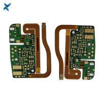
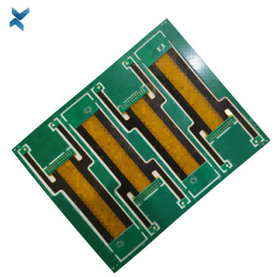
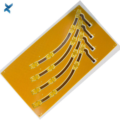
High Aspect FR4 FPC Rigid Flex PCB Board Immersion Gold Surface
Rigid Flex PCB High Aspect Ration Boards For Handheld Monitors
What is Rigid Flex?
Rigid flex printed circuit boards provide designers with one of the more unique packaging methods for electronic designs.
Combining the component and routing density of hardboards with the flexibility of flexible circuits, rigid flex PCBs allow designers to achieve routing density and interconnectivity that is not available in other types of circuit boards.
Primarily used in military, medical and camera applications, rigid flex PCBs comprise about 1% of the overall PCB market, but they are increasingly used in other electronic applications.
They cost more than traditional hard boards and flexible circuits due to the raw materials required; but, in the right applications, rigid flex PCBs dramatically outperform traditional rigid and flexible circuit boards, and they can be more cost-effective in a full solution.
When Should You Use Rigid Flex?
-
When a designer needs a flexible solution and needs to rout components on both sides of the PCB
-
When a designer requires electronics fit the device, rather than the device conform to the electronics
-
When the electronic components and connectivity required max out space for connectors and flex cables
-
As a single-package solution for electronics with high input/output connectivity
-
As a cost-effective alternative to a combined assembly of interconnected hard boards
-
When the designer has to miniaturize their design to accommodate greater functionality
-
In weight-saving applications, such as drones, unmanned vehicles, aerospace and space applications
-
In high vibration environments
-
In high shock applications, where electronics will be subjected to 10,000 G’s or more
-
In never-fail electronics
Features
- Available in layer counts above 20 layers for very high routing density
- Flexible layers typically 1, 2, 3 or 4, though more can be accommodated
- Controlled impedance in both rigid and flexible sections
- Very high reliability
- Minimum dielectrics: down to 1 mil in flex sections, 2 mil in rigid sections
- Largest library of rigid flex constructions approved to UL 94 V-0
- RoHS compliant
| YScircuit Rigid Flex PCB manufacturing capabilities overview |
| Feature | capabilities | |
| Layer Count | 2-20L | |
| Rigid-Flex Thickness | 0.3mm-5.0mm | |
| PCB thickness in flex section | 0.08-0.8mm | |
| copper Thickness | 1/4OZ-10OZ | |
| Minimum line Width and Space | 0.05mm/0.05mm(2mil/2mil) | |
| Stiffeners | Stainless steel,PI, FR4 etc. | |
| Material | Polyimide Flex+FR4,RA copper, HTE copper, polyimide, adhesive,Bondply | |
| Min mechanical Drilled Size | 0.15mm(6mil) | |
| Min laser Holes Size: | 0.075mm(3mil) | |
| Surface Finish | Suitable Microwave/RF PCB urface finishes: Electroless Nickel, Immersion Gold, ENEPIG, Lead free HASL,Immersion Silver.etc. | |
| Solder Mask | Green, Red, Yellow, Blue, White, Black, Purple, Matte Black, Matte green.etc. | |
| Covrelay (Flex Part) | Yellow Coverlay, WhiteCoverlay,Black Coverlay | |
| layer/m² | S<1㎡ | S<3㎡ | S<6㎡ | S<10㎡ | S<13㎡ | S<16㎡ | S<20㎡ | S<30㎡ | S<40㎡ | S<50㎡ | S<65㎡ | S<85㎡ | S<100㎡ |
| 1L | 4wds | 6wds | 7wds | 7wds | 9wds | 9wds | 10wds | 10wds | 10wds | 12wds | 14wds | 15wds | 16wds |
| 2L | 4wds | 6wds | 9wds | 9wds | 11wds | 12wds | 13wds | 13wds | 15wds | 15wds | 15wds | 15wds | 18wds |
| 4L | 6wds | 8wds | 12wds | 12wds | 14wds | 14wds | 14wds | 14wds | 15wds | 20wds | 25wds | 25wds | 28wds |
| 6L | 7wds | 9wds | 13wds | 13wds | 17wds | 18wds | 20wds | 22wds | 24wds | 25wds | 26wds | 28wds | 30wds |
| 8L | 9wds | 12wds | 15wds | 18wds | 20wds | 20wds | 22wds | 24wds | 26wds | 27wds | 28wds | 30wds | 30wds |
| 10L | 10wds | 13wds | 17wds | 18wds | 20wds | 20wds | 22wds | 24wds | 26wds | 27wds | 28wds | 30wds | 30wds |
| 12L | 10wds | 15wds | 17wds | 18wds | 20wds | 20wds | 22wds | 24wds | 26wds | 27wds | 28wds | 30wds | 30wds |
| 14L | 10wds | 16wds | 17wds | 18wds | 20wds | 20wds | 22wds | 24wds | 26wds | 27wds | 28wds | 30wds | 30wds |
| 16L | 10wds | 16wds | 17wds | 18wds | 20wds | 20wds | 22wds | 24wds | 26wds | 27wds | 28wds | 30wds | 30wds |
FQA
Q: What is the smallest PCB size I can have?
A: Printed circuit boards are used in a variety of electronic products and therefore can be manufactured in a number of sizes.
Board sizes vary, dependent on customer requirements with the smallest pcb size that we have made being only 5mm square, for a miniature medical device.
Your PCBs can be made in a size to suit your requirements, however, there are a number of factors to consider, including product size, single sided, double sided plated through hole or multilayer, as well as number and weight of components, and the board’s finished application.
Each panel of boards will require a border for tooling holes, traces and coupons, and space for routing. Large panels with many circuits often have a poor manufacturing strength and therefore need to be reinforced, whilst smaller circuit boards may be stronger.
Small and irregular shaped PCB’s can also be made using our precision CNC routing machine and left in a routed panel with pips, or rectangular boards can be scored with pips.
For more advice about PCB size, please get in touch any time.
Recommended Products