


All Products
Contact Person :
Zhou
Phone Number :
+86 15019457904
Whatsapp :
+8615019457904
1.5oz Rigid Flexible Printed Circuit Board for Cochlear Implants


| Place of Origin | China |
|---|---|
| Brand Name | YScircuit |
| Certification | ISO9001,UL,REACH, RoHS |
| Model Number | YS-RF-28 |
| Minimum Order Quantity | 1 |
| Price | 0.2-6$/pieces |
| Packaging Details | Foam cotton + carton + strap |
| Delivery Time | 2-8 work days |
| Payment Terms | T/T,PayPal, Alibaba pay |
| Supply Ability | 1580000 |

Contact me for free samples and coupons.
Whatsapp:0086 18588475571
Wechat: 0086 18588475571
Skype: sales10@aixton.com
If you have any concern, we provide 24-hour online help.
xProduct Details
| Name | Cochlear Implants PCB | Material | FR4-FPC |
|---|---|---|---|
| Surface Process | Immersion Gold | Size | 4.8*12cm |
| Thickness | 1mm | Layer | 2 Layers |
| Copper Thickness | 1.5oz | Application | Cochlear Implants |
| High Light | 1.5oz Rigid Flexible Printed Circuit Board,1.5oz Rigid Flex Circuits,1.5oz Rigid Flex Circuit Boards |
||
Product Description
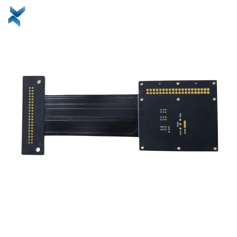
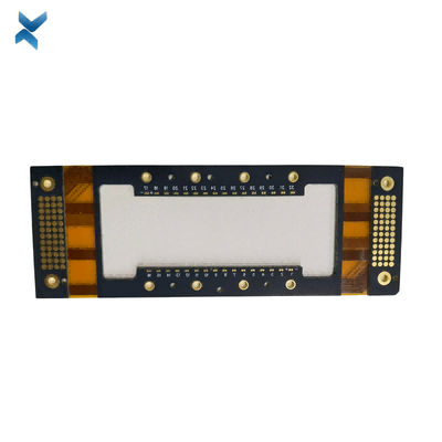
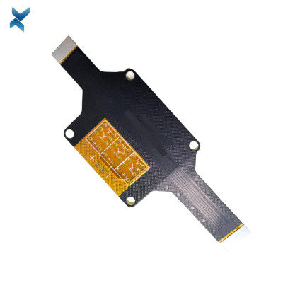
1.5oz Rigid Flexible Printed Circuit Board For Cochlear Implants
Rigid Flex PCB Differential Controlled Printed Circuit Boards For Cochlear Implants
Rigid Flex
Rigid flex circuits have been used in the military and aerospace industries for more than 40 years.
In rigid flex circuit boards, layers of flexible and rigid materials are used to create both rigid and flexible areas in a single package.
Rigid flex circuits combine the best of both rigid boards and flexible circuits integrated together into one circuit.
Rigid outer layers are connected to inner flexible layers using copper plated vias.
Rigid flex circuits provide higher component density and better quality control.
Designs are rigid where extra support for SMT components is needed, and is and flexible in areas that need to bend and flex to fit into tight spaces.
There are many high level benefits to Rigid Flex circuits including:
Connection Reliability – Connecting rigid layers with flexible cables is the foundation for combination rigid flex circuits.
Rigid flex constructions eliminate the need for board-to-board connectors or wiring harnesses to link rigid boards together.
4 Layer Rigid Flex
Lower Part Count – Compared to a traditional rigid board, rigid flex circuits require fewer parts and interconnections by eliminating wire harnesses and board-to board connectors.
Flexible Design Options –
At Flexible Circuit Technologies, we pride ourselves on guiding customers on the most complex of design challenges to provide the most reliable and cost-effective designs.
Rigid flex circuits can be designed to meet highly complex and unimaginable configurations by utilizing both rigid and flexible substrates.
Rigid flex circuit designs can incorporate any of the following:
-
Highly complex configurations
-
Controlled Impedance
-
High layer count
-
Reduced interconnections
High Density Applications – By eliminating interconnecting hardware, rigid flex can free up space allowing for higher connection density. More often than not, the rigid areas of a rigid flex circuit are utilized for high density SMT device population.
The flexible regions connecting the rigid areas allow the circuit to be formed into a 3-dimensional shape, with multiple interconnected rigid areas on different planes.
Package Size and Weight Reduction – Due to the ultra-thin nature of flexible circuit materials and the ability to create very narrow circuit traces, much higher connection density is possible along with a significant reduction in overall system weight.
The inherent lower mass of rigid flex makes this interconnect system ideal in high shock and vibration applications.
|
YScircuit Rigid Flex PCB manufacturing capabilities overview |
|
Feature |
capabilities |
|
|
Layer Count |
2-20L |
|
|
Rigid-Flex Thickness |
0.3mm-5.0mm |
|
|
PCB thickness in flex section |
0.08-0.8mm |
|
|
copper Thickness |
1/4OZ-10OZ |
|
|
Minimum line Width and Space |
0.05mm/0.05mm(2mil/2mil) |
|
|
Stiffeners |
Stainless steel,PI, FR4 etc. |
|
|
Material |
Polyimide Flex+FR4,RA copper, HTE copper, polyimide, adhesive,Bondply |
|
|
Min mechanical Drilled Size |
0.15mm(6mil) |
|
|
Min laser Holes Size: |
0.075mm(3mil) |
|
|
Surface Finish |
Suitable Microwave/RF PCB urface finishes: Electroless Nickel, Immersion Gold, ENEPIG, Lead free HASL,Immersion Silver.etc. |
|
|
Solder Mask |
Green, Red, Yellow, Blue, White, Black, Purple, Matte Black, Matte green.etc. |
|
|
Covrelay (Flex Part) |
Yellow Coverlay, WhiteCoverlay,Black Coverlay |
|
|
layer/m² |
S<1㎡ |
S<3㎡ |
S<6㎡ |
S<10㎡ |
S<13㎡ |
S<16㎡ |
S<20㎡ |
S<30㎡ |
S<40㎡ |
S<50㎡ |
S<65㎡ |
S<85㎡ |
S<100㎡ |
|
1L |
4wds |
6wds |
7wds |
7wds |
9wds |
9wds |
10wds |
10wds |
10wds |
12wds |
14wds |
15wds |
16wds |
|
2L |
4wds |
6wds |
9wds |
9wds |
11wds |
12wds |
13wds |
13wds |
15wds |
15wds |
15wds |
15wds |
18wds |
|
4L |
6wds |
8wds |
12wds |
12wds |
14wds |
14wds |
14wds |
14wds |
15wds |
20wds |
25wds |
25wds |
28wds |
|
6L |
7wds |
9wds |
13wds |
13wds |
17wds |
18wds |
20wds |
22wds |
24wds |
25wds |
26wds |
28wds |
30wds |
|
8L |
9wds |
12wds |
15wds |
18wds |
20wds |
20wds |
22wds |
24wds |
26wds |
27wds |
28wds |
30wds |
30wds |
|
10L |
10wds |
13wds |
17wds |
18wds |
20wds |
20wds |
22wds |
24wds |
26wds |
27wds |
28wds |
30wds |
30wds |
|
12L |
10wds |
15wds |
17wds |
18wds |
20wds |
20wds |
22wds |
24wds |
26wds |
27wds |
28wds |
30wds |
30wds |
|
14L |
10wds |
16wds |
17wds |
18wds |
20wds |
20wds |
22wds |
24wds |
26wds |
27wds |
28wds |
30wds |
30wds |
|
16L |
10wds |
16wds |
17wds |
18wds |
20wds |
20wds |
22wds |
24wds |
26wds |
27wds |
28wds |
30wds |
30wds |
![]()
![]()
![]()
![]()
FQA
Q: Can I have my printed circuit boards in a choice of colours?
A: The pcb colour choice is often important, particularly when the PCB will be on display in lighting, hi-fi equipment or consumer electronics devices. We have therefore selected a PCB colour choice to include:
Green, Blue, Black, Red and White.
Coloured boards are also useful to differentiate individual PCBs from each other (i.e. prototype boards compared to production boards), or when several circuit boards are used within one housing. Some companies also have their own corporate range of PCB colours.
The substrate itself is coloured by pigment in the epoxy resin, which is used together with glass-fibre reinforcement to make up the finished board, which sits beneath the copper tracks.
Our standard range of PCB colours is available for immediate manufacture, however, if you have a requirement for a specific colour, please contact us.
Recommended Products