


All Products
Contact Person :
Zhou
Phone Number :
+86 15019457904
Whatsapp :
+8615019457904
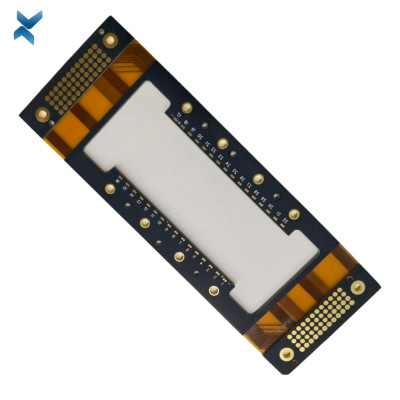
Thickness 1.2mm Rigid Flex PCB Board With Impedance Control


| Place of Origin | China |
|---|---|
| Brand Name | YScircuit |
| Certification | ISO9001,UL,REACH, RoHS |
| Model Number | YS-RF-27 |
| Minimum Order Quantity | 1 |
| Price | 0.2-6$/pieces |
| Packaging Details | Foam cotton + carton + strap |
| Delivery Time | 2-8 work days |
| Payment Terms | T/T,PayPal, Alibaba pay |
| Supply Ability | 1580000 |

Contact me for free samples and coupons.
Whatsapp:0086 18588475571
Wechat: 0086 18588475571
Skype: sales10@aixton.com
If you have any concern, we provide 24-hour online help.
xProduct Details
| Name | Pacemakers PCB | Material | FR4-FPC |
|---|---|---|---|
| Surface Process | Immersion Tin | Size | 5*12cm |
| Thickness | 1.2mm | Layer | 4 Layers |
| Copper Thickness | 1oz | Application | Pacemakers |
| High Light | 1.2mm Rigid Flex PCB Board,1oz Rigid Flex PCB Board,1.2mm Multilayer Flex PCB |
||
Product Description
Thickness 1.2mm Rigid Flex PCB Board With Impedance Control
Rigid Flex PCB Impedance Control Boards For Pacemakers Multilayer Boards
What is Rigid-Flex PCB:
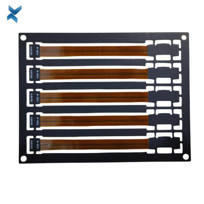
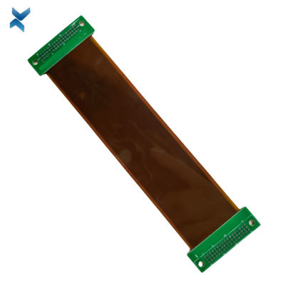
Rigid-Flex printed circuit boards are boards using a combination of flexible and rigid board technologies in an application.
Most rigid flex boards consist of multiple layers of flexible circuit substrates attached to one or more rigid boards externally and/or internally, depending upon the design of the application.
The flexible substrates are designed to be in a constant state of flex and are usually formed into the flexed curve during manufacturing or installation.
Rigid-Flex designs are more challenging than the design of a typical rigid board environment, as these boards are designed in a 3D space, which also offers greater spatial efficiency.
By being able to design in three dimensions rigid flex designers can twist, fold and roll the flexible board substrates to achieve their desired shape for the final application's package.
Rigid-Flex PCBs Fabrication Applications:
Rigid-Flex PCBs offer a wide array of applications, ranging from smart devices to cell phones and digital cameras.
Increasingly, rigid-flex board fabrication has been used in medical devices such as pacemakers for their space and weight reduction capabilities.
The same advantages for rigid-flex PCB usage can be applied to smart control systems.
In consumer products, rigid-flex doesn't just maximize space and weight but greatly improves reliability, eliminating many needs for solder joints and delicate, fragile wiring that are prone to connection issues.
These are just some examples, but Rigid-Flex PCBs can be used to benefit nearly all advanced electrical applications including testing equipment, tools and automobiles.
Rigid-Flex PCBs Technology and Production Process:
Whether producing a rigid flex prototype or production quantities requiring large scale Rigid-Flex PCBs fabrication and PCB assembly, the technology is well proven and reliable.
The flex PCB portion is particularly good in overcoming space and weight issues with spatial degrees of freedom.
Careful consideration of Rigid-Flex solutions and a proper assessment of the available options at the early stages in the rigid-flex PCB design phase will return significant benefits.
The Rigid-Flex PCBs fabricator must be involved early in the design process to ensure the design and fab portions are both in coordination and to account for final product variations.
The Rigid-Flex manufacturing phase is also more complex and time-consuming than rigid board fabrication.
All the flexible components of the Rigid-Flex assembly have completely different handling, etching, and soldering processes than rigid FR4 boards.
Benefits of Rigid-Flex PCBs
• Space requirements can be minimized by applying 3D
• By removing the need for connectors and cables between the individual rigid parts, the board size and overall system weight can be reduced.
• By maximizing space, there is often a lower count in parts.
• Fewer solder joints assure higher connection reliability.
• Handling during assembly is easier in comparison with flexible boards.
• Simplified PCB assembly processes.
• Integrated ZIF contacts provide simple modular interfaces to the system environment.
• Test conditions are simplified. A complete test before installation becomes possible.
• Logistical and assembly costs are significantly reduced with Rigid-Flex boards.
• It is possible to increase the complexity of mechanical designs, which also improves the degree of freedom for optimized housing solutions.
| YScircuit Rigid Flex PCB manufacturing capabilities overview |
| Feature | capabilities | |
| Layer Count | 2-20L | |
| Rigid-Flex Thickness | 0.3mm-5.0mm | |
| PCB thickness in flex section | 0.08-0.8mm | |
| copper Thickness | 1/4OZ-10OZ | |
| Minimum line Width and Space | 0.05mm/0.05mm(2mil/2mil) | |
| Stiffeners | Stainless steel,PI, FR4 etc. | |
| Material | Polyimide Flex+FR4,RA copper, HTE copper, polyimide, adhesive,Bondply | |
| Min mechanical Drilled Size | 0.15mm(6mil) | |
| Min laser Holes Size: | 0.075mm(3mil) | |
| Surface Finish | Suitable Microwave/RF PCB urface finishes: Electroless Nickel, Immersion Gold, ENEPIG, Lead free HASL,Immersion Silver.etc. | |
| Solder Mask | Green, Red, Yellow, Blue, White, Black, Purple, Matte Black, Matte green.etc. | |
| Covrelay (Flex Part) | Yellow Coverlay, WhiteCoverlay,Black Coverlay | |
| layer/m² | S<1㎡ | S<3㎡ | S<6㎡ | S<10㎡ | S<13㎡ | S<16㎡ | S<20㎡ | S<30㎡ | S<40㎡ | S<50㎡ | S<65㎡ | S<85㎡ | S<100㎡ |
| 1L | 4wds | 6wds | 7wds | 7wds | 9wds | 9wds | 10wds | 10wds | 10wds | 12wds | 14wds | 15wds | 16wds |
| 2L | 4wds | 6wds | 9wds | 9wds | 11wds | 12wds | 13wds | 13wds | 15wds | 15wds | 15wds | 15wds | 18wds |
| 4L | 6wds | 8wds | 12wds | 12wds | 14wds | 14wds | 14wds | 14wds | 15wds | 20wds | 25wds | 25wds | 28wds |
| 6L | 7wds | 9wds | 13wds | 13wds | 17wds | 18wds | 20wds | 22wds | 24wds | 25wds | 26wds | 28wds | 30wds |
| 8L | 9wds | 12wds | 15wds | 18wds | 20wds | 20wds | 22wds | 24wds | 26wds | 27wds | 28wds | 30wds | 30wds |
| 10L | 10wds | 13wds | 17wds | 18wds | 20wds | 20wds | 22wds | 24wds | 26wds | 27wds | 28wds | 30wds | 30wds |
| 12L | 10wds | 15wds | 17wds | 18wds | 20wds | 20wds | 22wds | 24wds | 26wds | 27wds | 28wds | 30wds | 30wds |
| 14L | 10wds | 16wds | 17wds | 18wds | 20wds | 20wds | 22wds | 24wds | 26wds | 27wds | 28wds | 30wds | 30wds |
| 16L | 10wds | 16wds | 17wds | 18wds | 20wds | 20wds | 22wds | 24wds | 26wds | 27wds | 28wds | 30wds | 30wds |
![]()
![]()
![]()
![]()
FQA
Q: Can I get my printed circuit boards in different thicknesses?
A: We accommodate PCB Thickness in a multitude of products and requirements. Standard thicknesses include 0.4mm to 1.6mm in 0.2 steps, as well as 2mm, 2.4mm and 3.2mm.
We have been designing and manufacturing printed circuit boards in the CN for more than 30 years.
Printed circuit boards can be single sided, double sided plated through hole or multi-layered. 1.6mm is still the standard thickness for multilayer boards, with sizes between 0.5mm – 3.2mm.
Our PCB board delivery times are among the best in the country. For more information and advice on the ideal circuit board for you, please contact us.
For more advice about PCB thickness, please contact us any time.
Recommended Products