


All Products
Contact Person :
Zhou
Phone Number :
+86 15019457904
Whatsapp :
+8615019457904
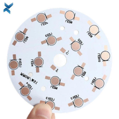
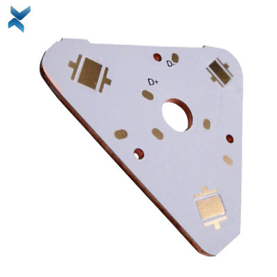
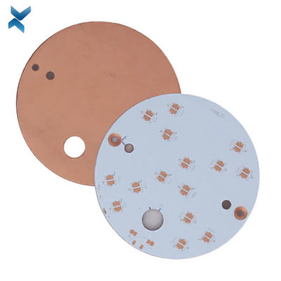
Immersion Gold Copper Metal Core PCB Round Shape For AC Converters


| Place of Origin | Shenzhen |
|---|---|
| Brand Name | YScircuit |
| Certification | ISO9001,UL,REACH, RoHS |
| Model Number | YS-MC-0013 |
| Minimum Order Quantity | 1 piece |
| Price | 0.02-8$/piece |
| Packaging Details | Foam cotton + carton + strap |
| Delivery Time | 2-8 days |
| Payment Terms | T/T,PayPal, Alibaba pay |
| Supply Ability | 251,000 square meter/year |

Contact me for free samples and coupons.
Whatsapp:0086 18588475571
Wechat: 0086 18588475571
Skype: sales10@aixton.com
If you have any concern, we provide 24-hour online help.
xProduct Details
| Material | Copper Base | Size | 6*6cm |
|---|---|---|---|
| Process | Immersion Gold | Surface Finishing | HASL/HASL-LF/ENIG/OSP |
| Shape | Round | Thickness | 0.2cm |
| Application | AC Converters | Name | AC Converters Pcb |
| High Light | Immersion Gold Copper Metal Core PCB,Round Copper Metal Core PCB |
||
Product Description
Copper Base PCB Board Metal Core Print Circuit Boards For AC Converters
Advantages of Copper Backed PCB
In a copper core PCB, the interconnections are performed using a copper track between the various components.
It makes the entire unit small enough to fit in a tiny device.
In case any part of the PCB is damaged, with transparent labeling on it, you can quickly replace the damaged parts instead of the whole component.
Also, the clear label makes the installation convenient.
The printed copper circuit board takes much less time to assemble compared to the conventional wire-based component connections.
Copper PCB is connected correctly with the use of solder flux.
Thus, the entire board is held together tightly.
It prevents their movement even if the board moves on the surface.
A copper PCB also eliminates the chance of short circuit or loose connections thanks to its tight attachment.
A correctly laid out copper printed circuit board reduces the noise quite significantly.
The reduced electronic noise enhances device performance.
Copper PCBs are highly reliable and cost-effective too.
Thus, it reduces the cost of electronic devices significantly and turns them affordable enough for general people.
Disadvantages of Copper Backed PCB
Copper PCBs can carry less current due it its small size.
Hence, its use is limited to small components only.
Its soldering needs extreme attention since the tiny size often leads to over-heating issues.
The over-heating can damage the entire component.
![]()
| Metal core PCB type | Normal single sided Aluminium based pcb, Double sided Aluminum pcb, FR4+Aluminium mixed backed circuit boards, Chip on board LED Alumnum pcb or copper pcb (COB MCPCB), Copper substrate pcb, LED PCB; |
| Board Material | Bergquist Aluminium material, Aluminum Base,Copper Base |
| LED PCB Max Dimension | 1900mm*480mm |
| Min Dimension | 5mm*5mm |
| Min Trace& line spacing | 0.1mm |
| Warp & Twist | <0.5mm |
| Finished MPCB Thickness | 0.2-4.5 mm |
| Copper Thickness | 18-240 um |
| Hole Inner Copper Thickness | 18-40 um |
| Hole Position Tolerance | +/-0.075 mm |
| Min Punching Hole Diameter | 1.0mm |
| Min Punching Square Slot Specification | 0.8mm*0.8mm |
| Silk Prints Circuit Tolerance | +/-0.075 mm |
| Outline Tolerance | CNC:+/-0.1mm; Mould:+/- 0.75mm |
| Min Hole Size | 0.2 mm (No limitation in Max hole dimention) |
| V-CUT Angle Deviation | +/-0.5° |
| V-CUT Board Thickness Range | 0.6mm-3.2mm |
| Min Component Mark Character Style | 0.15 mm |
| Min Open Window for PADs | 0.01mm |
| Solder Mask color | Green, White, Blue, Matte black, Red. |
| Surface Finishing | HASL, OSP, HASL LF, ENIG, ENEPIG (Electroless Nickel Electroless Palladium Immersion Gold) |
| layer/m² | S<1㎡ | S<3㎡ | S<6㎡ | S<10㎡ | S<13㎡ | S<16㎡ | S<20㎡ | S<30㎡ | S<40㎡ | S<50㎡ | S<65㎡ | S<85㎡ | S<100㎡ |
| 1L | 4wds | 6wds | 7wds | 7wds | 9wds | 9wds | 10wds | 10wds | 10wds | 12wds | 14wds | 15wds | 16wds |
| 2L | 4wds | 6wds | 9wds | 9wds | 11wds | 12wds | 13wds | 13wds | 15wds | 15wds | 15wds | 15wds | 18wds |
| 4L | 6wds | 8wds | 12wds | 12wds | 14wds | 14wds | 14wds | 14wds | 15wds | 20wds | 25wds | 25wds | 28wds |
| 6L | 7wds | 9wds | 13wds | 13wds | 17wds | 18wds | 20wds | 22wds | 24wds | 25wds | 26wds | 28wds | 30wds |
| 8L | 9wds | 12wds | 15wds | 18wds | 20wds | 20wds | 22wds | 24wds | 26wds | 27wds | 28wds | 30wds | 30wds |
| 10L | 10wds | 13wds | 17wds | 18wds | 20wds | 20wds | 22wds | 24wds | 26wds | 27wds | 28wds | 30wds | 30wds |
| 12L | 10wds | 15wds | 17wds | 18wds | 20wds | 20wds | 22wds | 24wds | 26wds | 27wds | 28wds | 30wds | 30wds |
| 14L | 10wds | 16wds | 17wds | 18wds | 20wds | 20wds | 22wds | 24wds | 26wds | 27wds | 28wds | 30wds | 30wds |
| 16L | 10wds | 16wds | 17wds | 18wds | 20wds | 20wds | 22wds | 24wds | 26wds | 27wds | 28wds | 30wds | 30wds |
Single Layer Metal Core PCB Stack up
![]()
Double Layer Metal Core PCB Stack up
![]()
Multilayer Metal Core PCB Stack up
![]()
![]()
![]()
![]()
![]()
![]()
FQA
1. What is the thickness of a metal core PCB?
The thickness of the metal core in a PCB substrate is typically 30 mil - 125 mil, but thicker and thinner boards are possible.
2. What are the advantages of metal core board?
Metal core boards transfer heat 8 to 9 times faster than FR4 PCBs.
These metal core laminates keep heat-generating components cool by dissipating heat faster.
The dielectric material is kept as thin as possible in order to create the shortest path from the heat source to the metal backplane.
3. How is a metal core PCB made?
If the board is a single-layer board with no layers transitioning back to the metal plate, the dielectric layers can be pressed and bonded to the metal plate using the standard process used with FR4 dielectrics.
4. What is a metal core PCB?
A metal core printed circuit board (MCPCB) is a printed circuit board that contains base metal materials.
The core is designed to transfer heat away from components that generate a lot of heat.
Recommended Products