


All Products
Contact Person :
Zhou
Phone Number :
+86 15019457904
Whatsapp :
+8615019457904
Metal Core 8oz Copper Base PCB Multilayer For DC Converters


| Place of Origin | Shenzhen |
|---|---|
| Brand Name | YScircuit |
| Certification | ISO9001,UL,REACH, RoHS |
| Model Number | YS-MC-0012 |
| Minimum Order Quantity | 1 piece |
| Price | 0.02-8$/piece |
| Packaging Details | Foam cotton + carton + strap |
| Delivery Time | 2-8 days |
| Payment Terms | T/T,PayPal, Alibaba pay |
| Supply Ability | 251,000 square meter/year |

Contact me for free samples and coupons.
Whatsapp:0086 18588475571
Wechat: 0086 18588475571
Skype: sales10@aixton.com
If you have any concern, we provide 24-hour online help.
xProduct Details
| Material | Copper Base | Size | According To Customer Request |
|---|---|---|---|
| Process | Immersion Gold | Surface Finishing | HASL/HASL-LF/ENIG/OSP |
| Board Thickness | 1.8mm | Cu Thickness | 8oz |
| Color | Brown | Application | Consumer Electronics |
| High Light | Copper Base PCB Metal Core,Multilayer Copper Base PCB,8oz copper metal core pcb |
||
Product Description
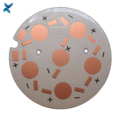
High Performance Copper Base Board Metal Core Pcba For DC Converters
Metal Core PCB Design Guidelines:
The MCPCB or metal core PCBs are manufactured around epoxy resin due to its adhesive capacity.
On each side, the PCB has copper substrate or foil, and the middle is sandwiched of a copper circuit board for high thermal and electric conductivity.
These are also known as metal-clad PCBs since the copper is one of the most used metals.
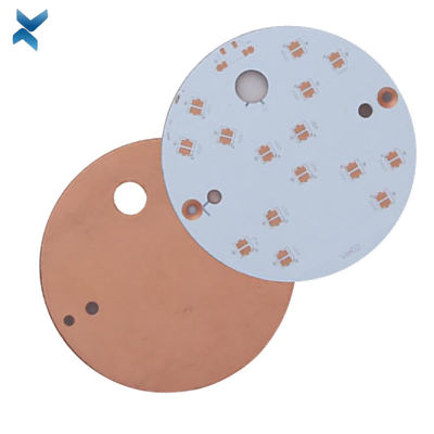
If the copper core manufacturer is developing a multilayer copper PCB, it will use two to three copper layers in the middle part to increase the conductivity.
The multilayer PCBs of copper are often embedded, which improves its performance and reliability.
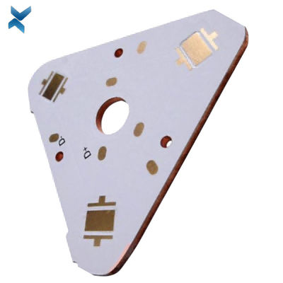
Sometimes, manufacturers use a heavy-copper base for the PCB.
These thick copper PCBs remain functional in the most extreme conditions.
Hence, electronic device producers use it for a variety of usage, such as UPS systems, nuclear power centers, renewable energies, and so on.
Single Layer Metal Core PCB Stack up
![]()
Double Layer Metal Core PCB Stack up
![]()
Multilayer Metal Core PCB Stack up
![]()
| Metal core PCB type | Normal single sided Aluminium based pcb, Double sided Aluminum pcb, FR4+Aluminium mixed backed circuit boards, Chip on board LED Alumnum pcb or copper pcb (COB MCPCB), Copper substrate pcb, LED PCB; |
| Board Material | Bergquist Aluminium material, Aluminum Base,Copper Base |
| LED PCB Max Dimension | 1900mm*480mm |
| Min Dimension | 5mm*5mm |
| Min Trace& line spacing | 0.1mm |
| Warp & Twist | <0.5mm |
| Finished MPCB Thickness | 0.2-4.5 mm |
| Copper Thickness | 18-240 um |
| Hole Inner Copper Thickness | 18-40 um |
| Hole Position Tolerance | +/-0.075 mm |
| Min Punching Hole Diameter | 1.0mm |
| Min Punching Square Slot Specification | 0.8mm*0.8mm |
| Silk Prints Circuit Tolerance | +/-0.075 mm |
| Outline Tolerance | CNC:+/-0.1mm; Mould:+/- 0.75mm |
| Min Hole Size | 0.2 mm (No limitation in Max hole dimention) |
| V-CUT Angle Deviation | +/-0.5° |
| V-CUT Board Thickness Range | 0.6mm-3.2mm |
| Min Component Mark Character Style | 0.15 mm |
| Min Open Window for PADs | 0.01mm |
| Solder Mask color | Green, White, Blue, Matte black, Red. |
| Surface Finishing | HASL, OSP, HASL LF, ENIG, ENEPIG (Electroless Nickel Electroless Palladium Immersion Gold) |
| layer/m² | S<1㎡ | S<3㎡ | S<6㎡ | S<10㎡ | S<13㎡ | S<16㎡ | S<20㎡ | S<30㎡ | S<40㎡ | S<50㎡ | S<65㎡ | S<85㎡ | S<100㎡ |
| 1L | 4wds | 6wds | 7wds | 7wds | 9wds | 9wds | 10wds | 10wds | 10wds | 12wds | 14wds | 15wds | 16wds |
| 2L | 4wds | 6wds | 9wds | 9wds | 11wds | 12wds | 13wds | 13wds | 15wds | 15wds | 15wds | 15wds | 18wds |
| 4L | 6wds | 8wds | 12wds | 12wds | 14wds | 14wds | 14wds | 14wds | 15wds | 20wds | 25wds | 25wds | 28wds |
| 6L | 7wds | 9wds | 13wds | 13wds | 17wds | 18wds | 20wds | 22wds | 24wds | 25wds | 26wds | 28wds | 30wds |
| 8L | 9wds | 12wds | 15wds | 18wds | 20wds | 20wds | 22wds | 24wds | 26wds | 27wds | 28wds | 30wds | 30wds |
| 10L | 10wds | 13wds | 17wds | 18wds | 20wds | 20wds | 22wds | 24wds | 26wds | 27wds | 28wds | 30wds | 30wds |
| 12L | 10wds | 15wds | 17wds | 18wds | 20wds | 20wds | 22wds | 24wds | 26wds | 27wds | 28wds | 30wds | 30wds |
| 14L | 10wds | 16wds | 17wds | 18wds | 20wds | 20wds | 22wds | 24wds | 26wds | 27wds | 28wds | 30wds | 30wds |
| 16L | 10wds | 16wds | 17wds | 18wds | 20wds | 20wds | 22wds | 24wds | 26wds | 27wds | 28wds | 30wds | 30wds |
![]()
![]()
![]()
![]()
![]()
FQA
1. What is the thickness of a metal core PCB?
The thickness of the metal core in a PCB substrate is typically 30 mil - 125 mil, but thicker and thinner boards are possible.
2. What are the advantages of metal core board?
Metal core boards transfer heat 8 to 9 times faster than FR4 PCBs.
These metal core laminates keep heat-generating components cool by dissipating heat faster.
The dielectric material is kept as thin as possible in order to create the shortest path from the heat source to the metal backplane.
3. How is a metal core PCB made?
If the board is a single-layer board with no layers transitioning back to the metal plate, the dielectric layers can be pressed and bonded to the metal plate using the standard process used with FR4 dielectrics.
4. What is a metal core PCB?
A metal core printed circuit board (MCPCB) is a printed circuit board that contains base metal materials.
The core is designed to transfer heat away from components that generate a lot of heat.
Recommended Products