


All Products
Contact Person :
Zhou
Phone Number :
+86 15019457904
Whatsapp :
+8615019457904
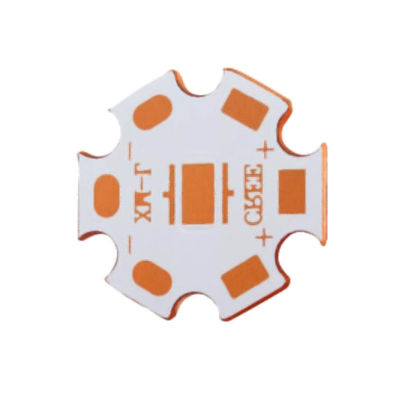
Electronics Aluminum Base PCB , 94v0 Circuit Board With Led Chips Car Light


| Place of Origin | Shenzhen |
|---|---|
| Brand Name | YScircuit |
| Certification | ISO9001,UL,REACH, RoHS |
| Model Number | YS-MC-0003 |
| Minimum Order Quantity | 1 piece |
| Price | 0.02-8$/piece |
| Packaging Details | Foam cotton + carton + strap |
| Delivery Time | 2-8 days |
| Payment Terms | T/T,PayPal, Alibaba pay |
| Supply Ability | 251,000 square meter/year |

Contact me for free samples and coupons.
Whatsapp:0086 18588475571
Wechat: 0086 18588475571
Skype: sales10@aixton.com
If you have any concern, we provide 24-hour online help.
xProduct Details
| Material | Copper Base | Size | According To Customer Request |
|---|---|---|---|
| Process | Immersion Gold/sliver | Surface Finishing | HASL/HASL-LF/ENIG/OSP |
| Board Thickness | 1.6mm | Copper Thickness | 0.5oz-8oz |
| Surface Finishing | HASL,OSP,Immersion Gold,HASL Lead Free | Application | Consumer Electronics |
| High Light | Electronics Aluminum Base PCB,94v0 Aluminum Base PCB,94v0 Circuit Board Led |
||
Product Description
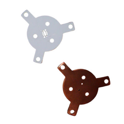
Aluminum Pcb Board With Led Chips 94v0 Mcpcb Board Copper Base Pcb For Car Light
YScircuit thermoelectric separation copper based PCB process steps:
1. First of all, cut the copper foil based PCB into a size that is suitable for processing.
2. Note that it needs to roughen the copper foil on the PCB surface with brushing, micro-etching and so on before squeezing film the based PCB.
3. Then, attach the dry film to the photoresist at an appropriate temperature and pressure, and it will create polymerization after being irradiated with ultraviolet light in the transparent area of the film, where the dry film will be reserved as an etching resist when developing and copper etching, however the circuit image on the film will be transferred to the dry film photoresist on the board.
4. Develop and remove the unexposed area on the film surface with an aqueous solution of sodium carbonate after peeling off the protective film on the film surface, and corrode and remove the exposed copper foil with a mixed solution of hydrochloric acid and hydrogen peroxide to form a circuit.
5.Finally, clean the dry film photoresist that has been finished with an an aqueous solution of sodium hydroxide. For six or more layers inner layer PCB, it can punch out the reference hole of the interlayer circuit with the automatic positioning punching machine.
Single Layer Metal Core PCB Stack up
![]()
Double Layer Metal Core PCB Stack up
![]()
Multilayer Metal Core PCB Stack up
![]()
| Metal core PCB type | Normal single sided Aluminium based pcb, Double sided Aluminum pcb, FR4+Aluminium mixed backed circuit boards, Chip on board LED Alumnum pcb or copper pcb (COB MCPCB), Copper substrate pcb, LED PCB; |
| Board Material | Bergquist Aluminium material, Aluminum Base,Copper Base |
| LED PCB Max Dimension | 1900mm*480mm |
| Min Dimension | 5mm*5mm |
| Min Trace& line spacing | 0.1mm |
| Warp & Twist | <0.5mm |
| Finished MPCB Thickness | 0.2-4.5 mm |
| Copper Thickness | 18-240 um |
| Hole Inner Copper Thickness | 18-40 um |
| Hole Position Tolerance | +/-0.075 mm |
| Min Punching Hole Diameter | 1.0mm |
| Min Punching Square Slot Specification | 0.8mm*0.8mm |
| Silk Prints Circuit Tolerance | +/-0.075 mm |
| Outline Tolerance | CNC:+/-0.1mm; Mould:+/- 0.75mm |
| Min Hole Size | 0.2 mm (No limitation in Max hole dimention) |
| V-CUT Angle Deviation | +/-0.5° |
| V-CUT Board Thickness Range | 0.6mm-3.2mm |
| Min Component Mark Character Style | 0.15 mm |
| Min Open Window for PADs | 0.01mm |
| Solder Mask color | Green, White, Blue, Matte black, Red. |
| Surface Finishing | HASL, OSP, HASL LF, ENIG, ENEPIG (Electroless Nickel Electroless Palladium Immersion Gold) |
| layer/m² | S<1㎡ | S<3㎡ | S<6㎡ | S<10㎡ | S<13㎡ | S<16㎡ | S<20㎡ | S<30㎡ | S<40㎡ | S<50㎡ | S<65㎡ | S<85㎡ | S<100㎡ |
| 1L | 4wds | 6wds | 7wds | 7wds | 9wds | 9wds | 10wds | 10wds | 10wds | 12wds | 14wds | 15wds | 16wds |
| 2L | 4wds | 6wds | 9wds | 9wds | 11wds | 12wds | 13wds | 13wds | 15wds | 15wds | 15wds | 15wds | 18wds |
| 4L | 6wds | 8wds | 12wds | 12wds | 14wds | 14wds | 14wds | 14wds | 15wds | 20wds | 25wds | 25wds | 28wds |
| 6L | 7wds | 9wds | 13wds | 13wds | 17wds | 18wds | 20wds | 22wds | 24wds | 25wds | 26wds | 28wds | 30wds |
| 8L | 9wds | 12wds | 15wds | 18wds | 20wds | 20wds | 22wds | 24wds | 26wds | 27wds | 28wds | 30wds | 30wds |
| 10L | 10wds | 13wds | 17wds | 18wds | 20wds | 20wds | 22wds | 24wds | 26wds | 27wds | 28wds | 30wds | 30wds |
| 12L | 10wds | 15wds | 17wds | 18wds | 20wds | 20wds | 22wds | 24wds | 26wds | 27wds | 28wds | 30wds | 30wds |
| 14L | 10wds | 16wds | 17wds | 18wds | 20wds | 20wds | 22wds | 24wds | 26wds | 27wds | 28wds | 30wds | 30wds |
| 16L | 10wds | 16wds | 17wds | 18wds | 20wds | 20wds | 22wds | 24wds | 26wds | 27wds | 28wds | 30wds | 30wds |
![]()
![]()
![]()
![]()
![]()
FQA
1. What is the thickness of a metal core PCB?
The thickness of the metal core in a PCB substrate is typically 30 mil - 125 mil, but thicker and thinner boards are possible.
2. What are the advantages of metal core board?
Metal core boards transfer heat 8 to 9 times faster than FR4 PCBs.
These metal core laminates keep heat-generating components cool by dissipating heat faster.
The dielectric material is kept as thin as possible in order to create the shortest path from the heat source to the metal backplane.
3. How is a metal core PCB made?
If the board is a single-layer board with no layers transitioning back to the metal plate, the dielectric layers can be pressed and bonded to the metal plate using the standard process used with FR4 dielectrics.
4. What is a metal core PCB?
A metal core printed circuit board (MCPCB) is a printed circuit board that contains base metal materials.
The core is designed to transfer heat away from components that generate a lot of heat.
Recommended Products