


All Products
Contact Person :
Zhou
Phone Number :
+86 15019457904
Whatsapp :
+8615019457904
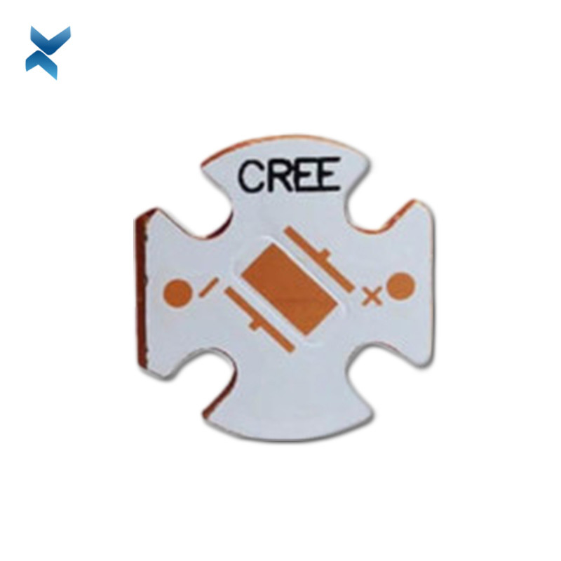
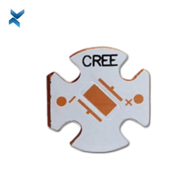
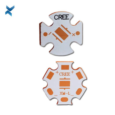
CREE XHP50 XHP70 Copper PCB Board Assembly For Led Chip Light


| Place of Origin | Shenzhen |
|---|---|
| Brand Name | YScircuit |
| Certification | ISO9001,UL,REACH, RoHS |
| Model Number | YS-MC-0004 |
| Minimum Order Quantity | 1 piece |
| Price | 0.04-8$/piece |
| Packaging Details | Foam cotton + carton + strap |
| Delivery Time | 2-8 days |
| Payment Terms | T/T,PayPal, Alibaba pay |
| Supply Ability | 251,000 square meter/year |

Contact me for free samples and coupons.
Whatsapp:0086 18588475571
Wechat: 0086 18588475571
Skype: sales10@aixton.com
If you have any concern, we provide 24-hour online help.
xProduct Details
| Material | Copper Base | Size | 2.2*2.2cm |
|---|---|---|---|
| Process | Immersion Gold/sliver | Surface Finishing | HASL/HASL-LF/ENIG/OSP |
| Color | Brown | Thickness | 0.16cm |
| Application | Balanced Amplifiers | Name | Balanced Amplifiers Pcb |
| High Light | XHP70 Copper PCB Board,XHP50 Copper PCB Board |
||
Product Description
Assembly PCB Prototype CREE XHP50 XHP70 Copper PCB Board For Led Chip Light
What is copper based PCB?
Copper based PCB is the most expensive in metal core PCB, which has a great thermal conductivity better than aluminum PCB and iron based PCB, applying to high frequency circuit design, and the areas where have a great change for high and low temperatures, as well as sophisticated communication equipment and architectural decoration industry.
There are all kinds of copper based PCB, such as immersion gold copper based PCB, silver plating copper based PCB, hot air soldering leveling (HASL) copper based PCB, anti-oxidation copper based PCB and son on.
There is great demand for current carrying in copper based PCB layer so that creating a thicker copper foil with 35μm~280μm, thermal conductivity insulating layer makes a great effect on copper based PCB, and thermal conductivity is mainly made up of aluminum oxide and silicon powder, as well as the polymer filled with epoxy resin,
what’s more, copper based PCB has a lot of advantages, such as low thermal resistance with 0.15, good viscoplastic property, ability to withstand thermal aging, as well as mechanical and thermal stress.
Copper based PCB metal substrate plays an important role in copper based PCB, which is the support component of copper based PCB, mainly playing an important role in heat dissipation, shielding, covering or grounding.
But it needs to have a high thermal conductivity, applying to some normal mechanical process, such as drilling, punching, and cutting and so on.
![]()
| Metal core PCB type | Normal single sided Aluminium based pcb, Double sided Aluminum pcb, FR4+Aluminium mixed backed circuit boards, Chip on board LED Alumnum pcb or copper pcb (COB MCPCB), Copper substrate pcb, LED PCB; |
| Board Material | Bergquist Aluminium material, Aluminum Base,Copper Base |
| LED PCB Max Dimension | 1900mm*480mm |
| Min Dimension | 5mm*5mm |
| Min Trace& line spacing | 0.1mm |
| Warp & Twist | <0.5mm |
| Finished MPCB Thickness | 0.2-4.5 mm |
| Copper Thickness | 18-240 um |
| Hole Inner Copper Thickness | 18-40 um |
| Hole Position Tolerance | +/-0.075 mm |
| Min Punching Hole Diameter | 1.0mm |
| Min Punching Square Slot Specification | 0.8mm*0.8mm |
| Silk Prints Circuit Tolerance | +/-0.075 mm |
| Outline Tolerance | CNC:+/-0.1mm; Mould:+/- 0.75mm |
| Min Hole Size | 0.2 mm (No limitation in Max hole dimention) |
| V-CUT Angle Deviation | +/-0.5° |
| V-CUT Board Thickness Range | 0.6mm-3.2mm |
| Min Component Mark Character Style | 0.15 mm |
| Min Open Window for PADs | 0.01mm |
| Solder Mask color | Green, White, Blue, Matte black, Red. |
| Surface Finishing | HASL, OSP, HASL LF, ENIG, ENEPIG (Electroless Nickel Electroless Palladium Immersion Gold) |
| layer/m² | S<1㎡ | S<3㎡ | S<6㎡ | S<10㎡ | S<13㎡ | S<16㎡ | S<20㎡ | S<30㎡ | S<40㎡ | S<50㎡ | S<65㎡ | S<85㎡ | S<100㎡ |
| 1L | 4wds | 6wds | 7wds | 7wds | 9wds | 9wds | 10wds | 10wds | 10wds | 12wds | 14wds | 15wds | 16wds |
| 2L | 4wds | 6wds | 9wds | 9wds | 11wds | 12wds | 13wds | 13wds | 15wds | 15wds | 15wds | 15wds | 18wds |
| 4L | 6wds | 8wds | 12wds | 12wds | 14wds | 14wds | 14wds | 14wds | 15wds | 20wds | 25wds | 25wds | 28wds |
| 6L | 7wds | 9wds | 13wds | 13wds | 17wds | 18wds | 20wds | 22wds | 24wds | 25wds | 26wds | 28wds | 30wds |
| 8L | 9wds | 12wds | 15wds | 18wds | 20wds | 20wds | 22wds | 24wds | 26wds | 27wds | 28wds | 30wds | 30wds |
| 10L | 10wds | 13wds | 17wds | 18wds | 20wds | 20wds | 22wds | 24wds | 26wds | 27wds | 28wds | 30wds | 30wds |
| 12L | 10wds | 15wds | 17wds | 18wds | 20wds | 20wds | 22wds | 24wds | 26wds | 27wds | 28wds | 30wds | 30wds |
| 14L | 10wds | 16wds | 17wds | 18wds | 20wds | 20wds | 22wds | 24wds | 26wds | 27wds | 28wds | 30wds | 30wds |
| 16L | 10wds | 16wds | 17wds | 18wds | 20wds | 20wds | 22wds | 24wds | 26wds | 27wds | 28wds | 30wds | 30wds |
Single Layer Metal Core PCB Stack up
![]()
Double Layer Metal Core PCB Stack up
![]()
Multilayer Metal Core PCB Stack up
![]()
![]()
![]()
![]()
![]()
![]()
FQA
1. What is the thickness of a metal core PCB?
The thickness of the metal core in a PCB substrate is typically 30 mil - 125 mil, but thicker and thinner boards are possible.
2. What are the advantages of metal core board?
Metal core boards transfer heat 8 to 9 times faster than FR4 PCBs.
These metal core laminates keep heat-generating components cool by dissipating heat faster.
The dielectric material is kept as thin as possible in order to create the shortest path from the heat source to the metal backplane.
3. How is a metal core PCB made?
If the board is a single-layer board with no layers transitioning back to the metal plate, the dielectric layers can be pressed and bonded to the metal plate using the standard process used with FR4 dielectrics.
4. What is a metal core PCB?
A metal core printed circuit board (MCPCB) is a printed circuit board that contains base metal materials.
The core is designed to transfer heat away from components that generate a lot of heat.
Recommended Products