


All Products
Contact Person :
Zhou
Phone Number :
+86 15019457904
Whatsapp :
+8615019457904
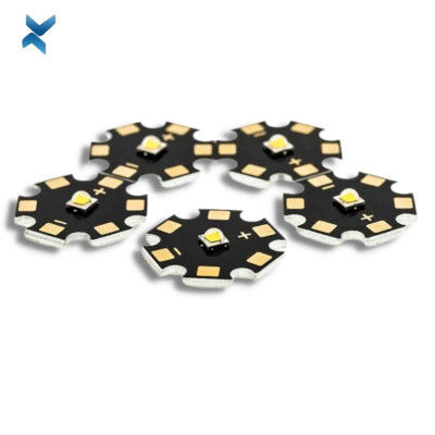
18cm Size LED Aluminum Plate PCB Board For Power Transmission Systems


| Place of Origin | Shenzhen |
|---|---|
| Brand Name | YScircuit |
| Certification | ISO9001,UL,REACH, RoHS |
| Model Number | YS-LE-00016 |
| Minimum Order Quantity | 1 piece |
| Price | 0.04-5$/piece |
| Packaging Details | Foam cotton + carton + strap |
| Delivery Time | 2-8 days |
| Payment Terms | T/T,PayPal, Alibaba pay, L/C |
| Supply Ability | 251,000 square meter/year |

Contact me for free samples and coupons.
Whatsapp:0086 18588475571
Wechat: 0086 18588475571
Skype: sales10@aixton.com
If you have any concern, we provide 24-hour online help.
xProduct Details
| Material | Metal+Components | Size | 18*18cm |
|---|---|---|---|
| Color | Black | Surface Finishing | HASL/HASL-LF/ENIG/OSP |
| Base Material | Aluminum | Min. Line Spacing | 2mil |
| Application | Power Transmission Systems | Name | Power Transmission Systems Pcb |
| High Light | 18cm LED Aluminum Plate PCB Board,LED Aluminum Plate PCB Board |
||
Product Description
Long Size LED Print Circuit Boards Thin Pcb For Power Transmission Systems
Aluminum LED Circuit Boards
Aluminum PCBs are the most common type of LED PCB.
These boards sit on an aluminum alloy base, which often consists of aluminum, magnesium and silicon.
These LED PCB materials alter the properties of the material to help meet the needs of each application.
Aluminum PCBs consist of several layers.
The base layer: The base layer includes an aluminum alloy sheet, and is the layer the rest of the PCB sits upon.
The thermal insulation layer: The thermal insulation layer consists of a ceramic polymer and protects the board from thermal and mechanical damage.
As the current travels throughout the circuits, this layer absorbs any heat given off and transfers it to the aluminum layer, where it disperses.
The circuit layer: This layer contains the copper circuits laid out according to the LED PCB’s circuit design.
PCBs have different numbers of these layers, depending on the board’s design.
There are several types of aluminum LED PCBs, which offer different characteristics that make them ideal for various applications.
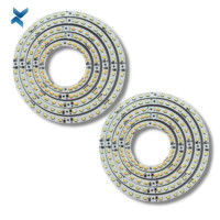
Flexible aluminum: Flexible LED PCBs consist of aluminum, polyimide resin and ceramic fillers, which give it increased flexibility and insulation, while retaining the aluminum’s thermal conductivity.
You can flex these PCBs to connect them, eliminating the need for connectors, cables and other fixtures.
However, their design enables them to bend once and get put in place, rather than flexing constantly.
These boards differ from the standard rigid boards, which do not bend.
Hybrid aluminum: Creating these types of boards involves fusing an aluminum base metal with a non-thermal material, such as a conventional FR-4 board.
Using this type of board reduces costs and increases rigidity while offering excellent heat dissipation.
Multilayer aluminum: Multilayer aluminum PCBs have more than two layers made of thermally conductive dielectrics.
These boards enable high performance, while still providing effective heat dissipation, although they are less effective at transferring heat than some other types of boards.
These boards differ from the simpler one- and two-layer PCBs.
| Layer | 1-24 |
| Material | Aluminum core (Domestic 1060), Copper core, FR4 covering |
| Thickness (Finished Board) | 0.8 mm-5.0 mm |
| Max. Board Size | 610 mm*610 mm |
| Copper weight (finished) | 0.5 oz-4.0 oz |
| Surface Finish | Hot air solder leveling (HASL) Lead-free HASL: RoHS compliant Electroless nickel/immersion gold (ENIG): RoHS compliant |
| Min. Tracing/Spacing | 4 mil/4 mil |
| Min. diameter of drill | 8mil |
| Min. Annular ring | 4mil |
| Soldermask Color | Green, red, black, yellow, white, blue, green matt, black matt |
| Silkscreen Legend Color | White, Black, Yellow |
| Countersink holes | Yes |
| Screw holes | Yes |
| layer/m² | S<1㎡ | S<3㎡ | S<6㎡ | S<10㎡ | S<13㎡ | S<16㎡ | S<20㎡ | S<30㎡ | S<40㎡ | S<50㎡ | S<65㎡ | S<85㎡ | S<100㎡ |
| 1L | 4wds | 6wds | 7wds | 7wds | 9wds | 9wds | 10wds | 10wds | 10wds | 12wds | 14wds | 15wds | 16wds |
| 2L | 4wds | 6wds | 9wds | 9wds | 11wds | 12wds | 13wds | 13wds | 15wds | 15wds | 15wds | 15wds | 18wds |
| 4L | 6wds | 8wds | 12wds | 12wds | 14wds | 14wds | 14wds | 14wds | 15wds | 20wds | 25wds | 25wds | 28wds |
| 6L | 7wds | 9wds | 13wds | 13wds | 17wds | 18wds | 20wds | 22wds | 24wds | 25wds | 26wds | 28wds | 30wds |
| 8L | 9wds | 12wds | 15wds | 18wds | 20wds | 20wds | 22wds | 24wds | 26wds | 27wds | 28wds | 30wds | 30wds |
| 10L | 10wds | 13wds | 17wds | 18wds | 20wds | 20wds | 22wds | 24wds | 26wds | 27wds | 28wds | 30wds | 30wds |
| 12L | 10wds | 15wds | 17wds | 18wds | 20wds | 20wds | 22wds | 24wds | 26wds | 27wds | 28wds | 30wds | 30wds |
| 14L | 10wds | 16wds | 17wds | 18wds | 20wds | 20wds | 22wds | 24wds | 26wds | 27wds | 28wds | 30wds | 30wds |
| 16L | 10wds | 16wds | 17wds | 18wds | 20wds | 20wds | 22wds | 24wds | 26wds | 27wds | 28wds | 30wds | 30wds |
![]()
![]()
![]()
![]()
![]()
FQA
1. The advantages of LED PCB
With the electronic products is more and more smaller and thinner, making it popular to use LED PCB, and there are various advantages with using LED PCB as follows:
- Lightweight, low profile
- dimensional stability
- thermal expansion
- heat dissipation
- Lower cost backlit membrane switch
- Dust and moisture resistant
- Make it easy to integrate into complex interface assemblies
- Efficient low power consumption
- Available in a wide variety of sizes, colors, and intensities
- May be used in silver flex membrane switches and copper flex membrane switches.
There are two main reasons which make the LED PCB be popular in addition to increasing the light output of the fixture with integrating multiple LED components.
- It’s easy to tune the color function by integrating the LED components with different color temperatures or different colors into the same PCB.
- It can achieve the various light fixtures to meet different lighting requirements with the boards that have different shapes, sizes and materials.
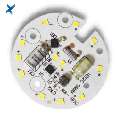
2. SMD LEDs in your PCB
There are many devices including LEDs on a PCB using surface mounted components.
If the wires are quite thin, through hole components can bend slightly so that it looks cheap from the outside.
If making it right to solder the SMD LED, it will be rigid on the board. What’s more, it can also place the SMD LED behind a screen, and cheaper LED that use a bulb will stick out through the packaging.
So it can place the SMD LED behind a small screen in your packaging to be cleaner for your device.
As you know, many PCBs that contain LEDs are fabricated with multilayer FR-4 substrates, so you need to have a pattern of closely-spaced filled or plated through vias under each component so that it can transmit heat, as well as get to your power and ground layers.
If your LEDs have a small footprint and are surfaced mounted, it can use our vias.
Probably there will be a weak solder joint or even tombstoning because it doesn’t fill or plate over the vias and then solder can wick into the vias during assembly, so the reason why it’s better to just use SMD LEDs on an LED lighting array is that the problem with wicking.
A single LED with decent power output will not lead to damaging to your board because of undue thermal.
However, if you are going to have a system for lighting applications, it will need to suffer from a massive heat for the board that supports your LEDs, and make it hard to cool with traditional methods for the boards.
Because the individual LEDs are too small, you can’t really attach a heatsink anywhere, and a heatsink will block the emitted light anyways.
Because there is a great demand on thermal, the boards with a metal core are usually used in LED lighting applications due to their ability to dissipate a great deal of heat.
In general, aluminum is used for LED lighting applications as the metal core in PCB.
What’s more, aluminum is the most metal used as the core among all the possible metal core PCBs.
As well as copper and iron are used for metal core PCBs.
Recommended Products